Define acceptance
Confirm code content, contrast, permanence, depth and any barcode or vision criteria.
Industrial laser technology selection
The useful difference is not the name or wattage—it is how the wavelength interacts with your material and whether the resulting mark meets the production requirement.
Start with the finished substrate and required result. CO₂ is commonly considered for cartons, labels, many films and plastics, glass, wood and organic materials. Fibre is often preferred for metals and selected rigid plastics. UV can suit fine, sensitive or difficult-to-mark polymers and packaging where lower heat input is valuable. These are starting points, not substitutes for sample trials.
At-a-glance comparison
The table describes common industrial tendencies. Pigments, additives, coatings and construction can change the answer.
| Decision factor | CO₂ laser | Fibre laser | UV laser |
|---|---|---|---|
| Common strengths | Packaging, paperboard, labels, selected films and plastics, glass, wood and organics. | Bare and coated metals, engineered components and selected high-density plastics. | Fine, high-contrast marking on selected plastics, films, glass and heat-sensitive materials. |
| Typical mark | Ablation of print or coating, engraving, etching or surface colour change. | Annealing, engraving, ablation, foaming or colour change depending on material. | Photochemical or fine surface change with a smaller heat-affected area. |
| Packaging role | Dates, batches, logos and 2D codes on many non-metal packs. | Metal caps, foils and selected rigid plastic packaging or components. | Selected mono-material films, delicate plastics and high-detail pack marks. |
| Main caution | Not the default for bare metal; thin or sensitive materials may be unsuitable. | Transparent and organic materials may absorb poorly; not universal on plastic. | Application window, throughput and project cost must be assessed against the benefit. |
| Evidence needed | Finished samples, exact code, target contrast, allowable surface change, line speed, mark area, geometry and environmental conditions. | ||
Why material names mislead
Two items described as PET, HDPE, polypropylene or another polymer can respond differently because of colour, fillers, recycled content, processing, coatings and wall thickness. A good trial uses the finished product from each intended supplier.
The required result matters too. A subtle permanent mark may suit human-readable text but fail a barcode contrast or grading requirement. Conversely, an aggressive mark may read well but be unacceptable on a thin, pressurised or barrier-sensitive pack.
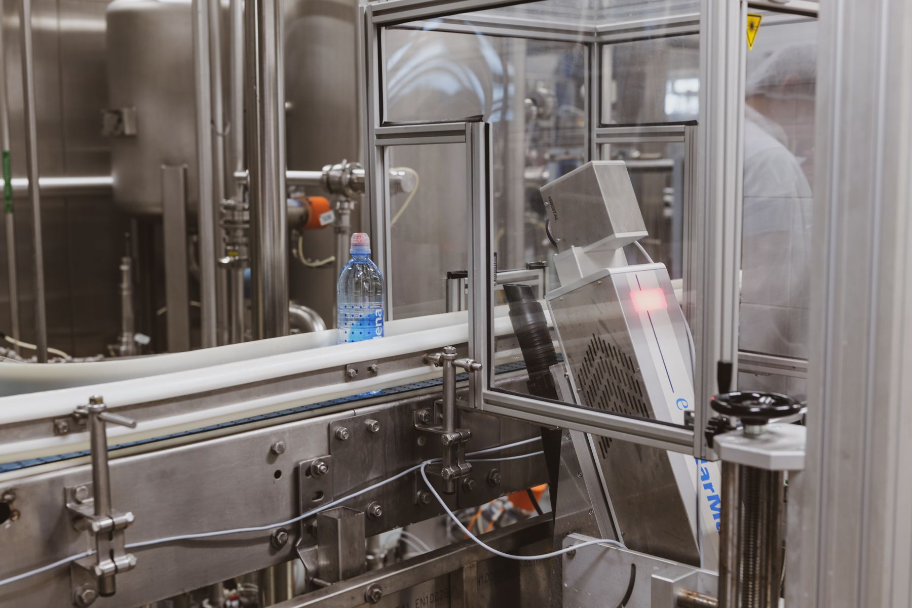
Selection sequence
A higher wattage is not automatically a better machine. A robust specification works through the application in order.
Confirm code content, contrast, permanence, depth and any barcode or vision criteria.
Test the likely CO₂, fibre or UV sources on all representative materials.
Use the worst-case code and available marking time, not a simple sample logo.
Balance marking field, spot behaviour, working distance and required detail.
Keep the surface stable within the proven focal and positional range.
Add controls, guarding, interlocks, extraction, verification and maintainable access.
Laser selection FAQs
Use these answers to choose trial routes, not to skip testing.
Arrange comparative trials ↗They use different wavelengths, so materials absorb their energy differently. CO₂ is commonly considered for packaging and organic materials, fibre for metals and selected rigid plastics, and UV for fine or heat-sensitive applications. The exact product must still be tested.
No single laser source is best for every plastic. Resin, colour, additives, fillers, wall thickness, surface finish and required mark can make CO₂, fibre or UV the better route.
CO₂ is not normally the first choice for bare metals because they do not efficiently absorb its common infrared wavelength. It can sometimes interact with coated or painted metal surfaces, while fibre is typically assessed for direct metal marking.
Usually no. Start with substrate response, required mark and wavelength, then size power, lens, field and scan strategy around the code and production speed.
Continue comparing
After the source is narrowed, compare the laser process with the inkjet or thermal technology it may replace, then budget for the complete guarded and extracted installation.
Best evidence: mark the same finished sample with each plausible source, using the real code and production-time constraint. Compare readability, permanence, surface effect and integration needs.
Planning a laser marking project?
Send us your product, code requirement and line speed. We’ll advise on the right next step.
Request an application review →